Xcelerator · Digital Thread Demonstrator
An autonomous AI agent authored a complete, cross-domain engineering design for the QX-250 quadcopter — from requirements to a running item structure in Teamcenter — inside the real Siemens Xcelerator tools. Not a mock-up. The actual CAD, EDA, and PLM systems.
The moment
“Watson, come here — I want to see you.” In 1876 one sentence proved a whole new medium was real. This is that kind of threshold — the first time an AI carried a single design idea, unbroken, through every discipline of a modern engineering enterprise and committed it to the system of record.
Alexander Graham Bell didn't just transmit a voice; he collapsed the distance between intent and reception. The digital thread has the same ambition — collapse the distance between a requirement and the as-built configuration, across mechanical, electrical, software, and reliability engineering, so nothing is lost in translation between tools or teams.
What's documented below is a live demonstration of that thread being authored end-to-end by an agent: reliability physics in MADe becoming requirements; requirements becoming functions; functions becoming a logical architecture; the architecture becoming an electrical schematic and wiring harness in Capital and a mechanical assembly in NX; and all of it materialized as configuration-managed items in Teamcenter. One idea. Every domain. No handoff lost.
The aircraft
A 5-inch freestyle-class quadcopter — the vehicle the whole thread describes.
≤ 700 g design limit
≥ 2:1 required at WOT
R(1 h), λ = 185 /10⁶ h (MADe)
per hour — 24 order-1 cut sets
| Domain | Configuration | Domain | Configuration |
|---|---|---|---|
| Airframe | Quad-X, 250 mm wheelbase, 3K carbon, 4 mm arms | Battery | 4S1P LiPo, 14.8 V, 1500 mAh |
| Motors | 4× 2306, 1700 KV, 3-phase BLDC | ESC | 4-in-1, 45 A, DShot600 |
| Props | 4× 5″ tri-blade (2 CW / 2 CCW) | Flight controller | STM32F7, MPU-6000 IMU, DPS310 baro |
| Control link | ELRS 2.4 GHz, CRSF | Endurance | ≥ 8 min hover |
The thread
Each stage is real work in the real tool. Screenshots are captured directly from the running applications.
The design starts from failure physics, not geometry. A MADe (PHM) model of the quadcopter produced an FMECA, a fault tree, and an RBD: loss-of-thrust probability 1.85×10⁻⁴/h, mission reliability R(1h)=0.99982, and — critically — 24 order-1 minimal cut sets: every single fault drops the aircraft, because a quad cannot fly on three rotors. That finding drives the safety requirements and a recommendation to trade toward a hexacopter.
50 requirements across 10 domains, with the reliability set traced line-by-line to the MADe artifacts. Nine functions (F1–F9: store energy, distribute power, drive motor, convert to rotation, generate thrust, sense, stabilize, receive command, provide structure) with a Quad-X mixer. Seven logical blocks and a ten-interface register, each function allocated to a block and every interface accounted for.
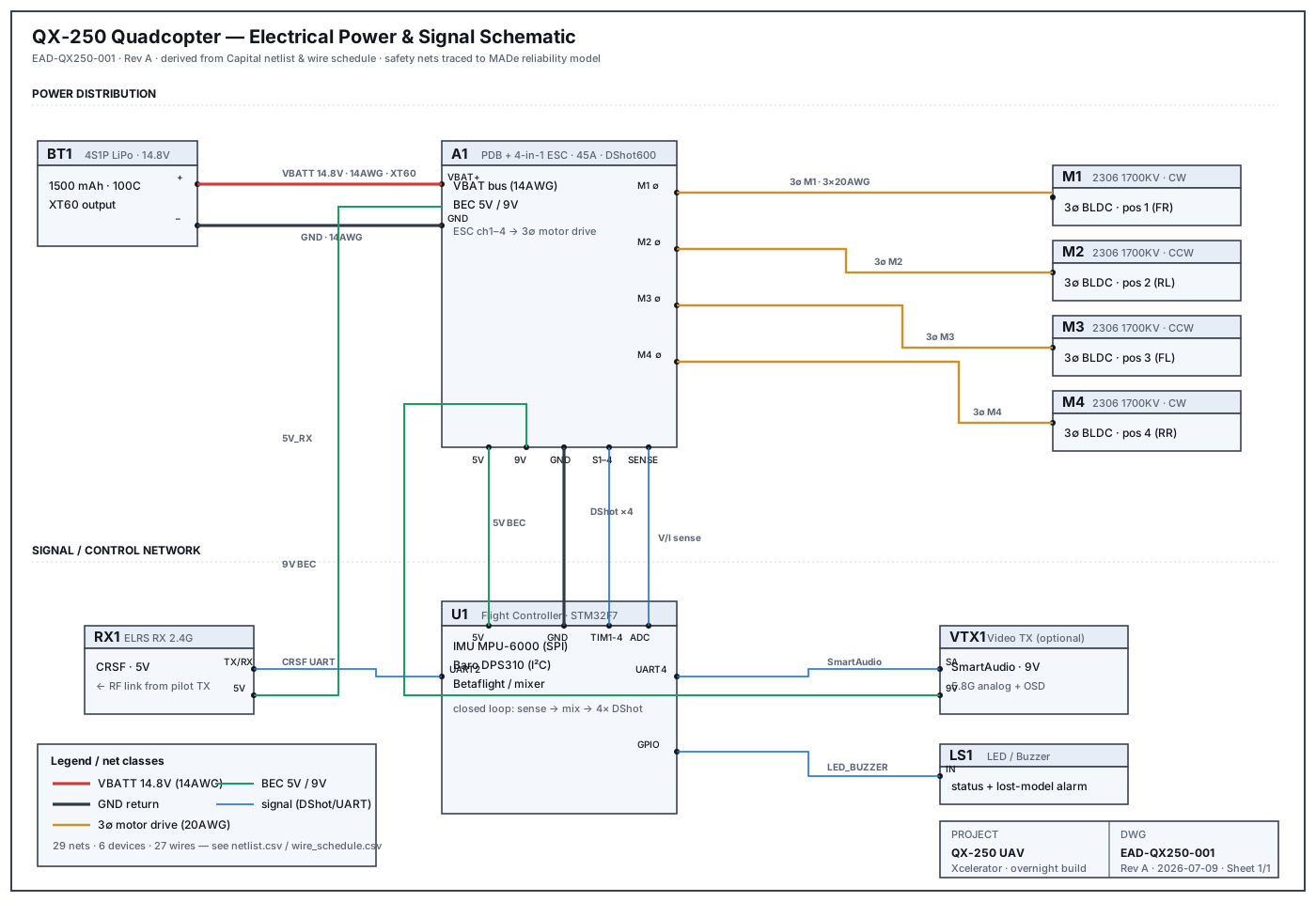
The power and signal architecture as a wiring schematic: a 4S battery feeds a 4-in-1 ESC that drives four 3-phase motors; an F7 flight controller closes the loop over DShot600, takes commands over an ELRS/CRSF link, and reads voltage/current sense. 29 nets, 27 wires, connector pinouts.
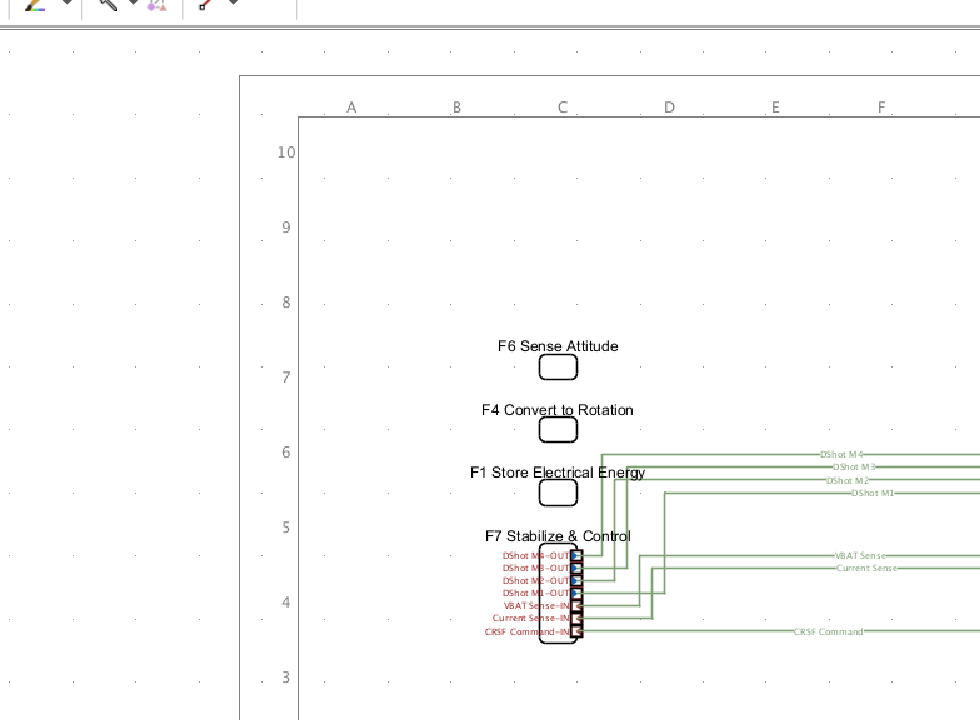
The functional architecture was authored natively in Capital Systems Architect: nine functions with their signal connectivity, generated as a live diagram in the tool. Then the platform architecture was synthesized into a Capital Logic Designer logic design — the automated bridge from architecture to schematic — surfacing the two active controllers (the 4-in-1 ESC and the F7 flight controller) with the full harness toolset (devices, conductors, multicores, highways) ready for detailing.
The complete device-level wiring (all 10 devices, 29 nets) is the authored schematic in stage 2; the physical wiring harness is realized in 3D in NX below.
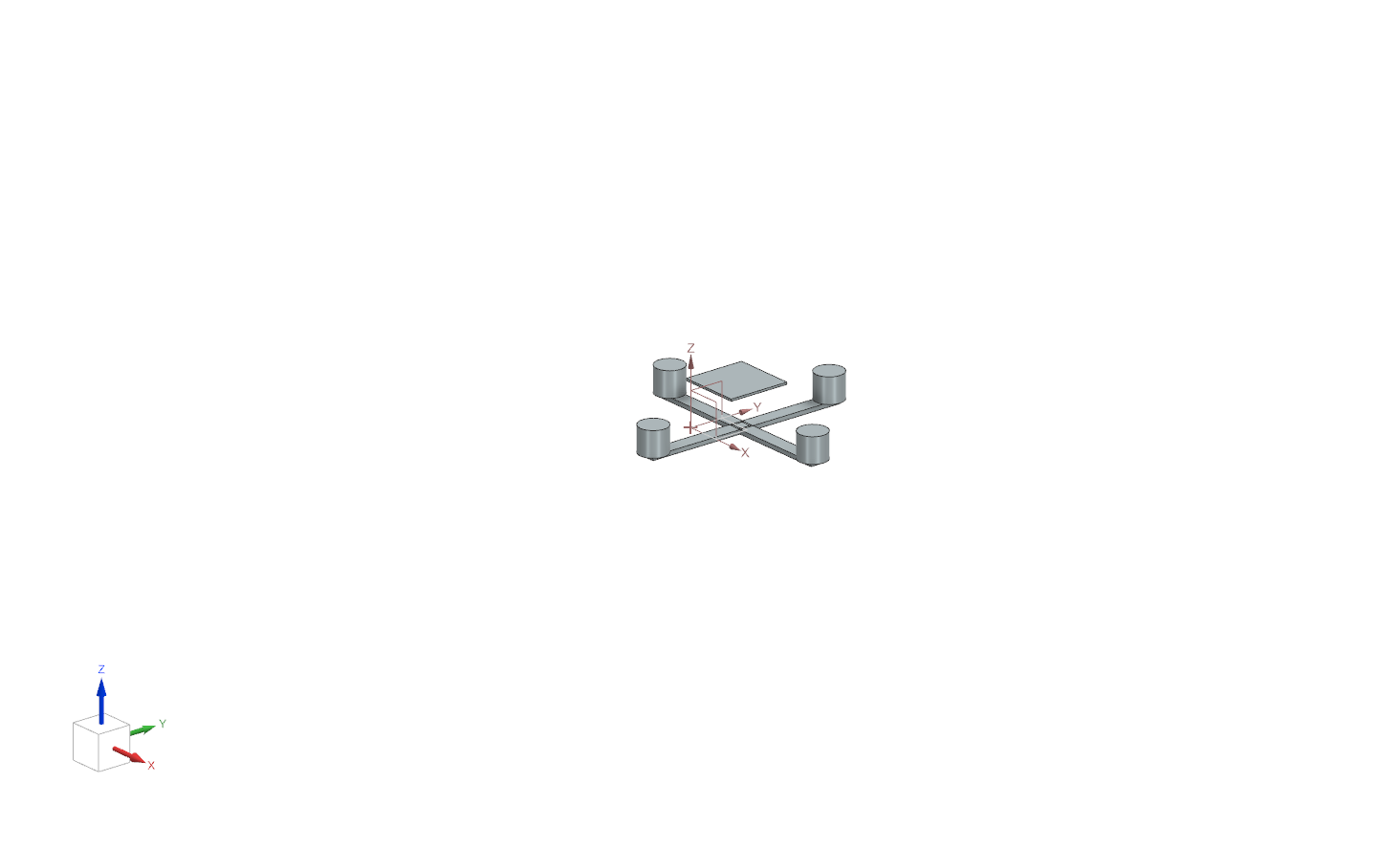
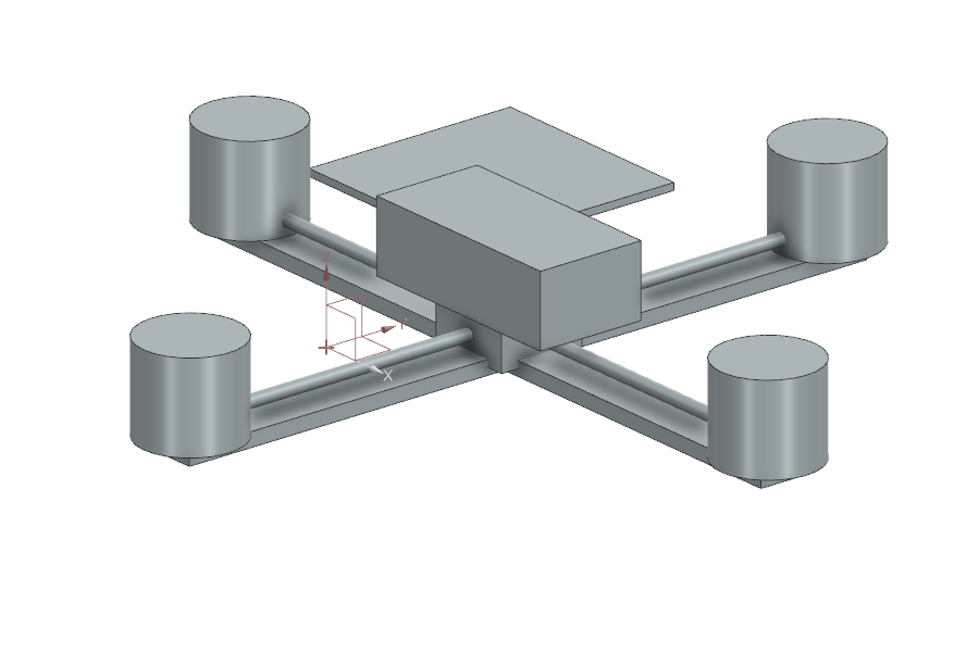
The airframe in Siemens NX, taken from a conceptual frame to a finished assembly: the parametric Quad-X frame (250 mm wheelbase, central plate, four circular-patterned arms, a motor on each arm) now carries the electronics stack (PDB/ESC + flight controller), the LiPo battery, and — the key step — the motor wiring routed in 3D: a wire run from the central stack out along each arm to its motor, patterned four-up. That's the harness realized physically, closing the loop from the Capital schematic to real geometry.
The whole logical architecture was pushed into the live Pre-Integration Teamcenter over the SOA gateway: 57 items (components → Fnd0LogicalBlock, functions → Functionality, carriers, signals, Fnd0LogicConn connections, Seg0Interface contracts) and 115 relations (all function→component allocations, interface contracts, trace links). Verified by read-back. This is the system of record — the as-designed configuration now lives in PLM.
How it was built
The hard part of a digital thread isn't any one tool — it's the seams. Here's how the seams were crossed.
Maintenance-Aware Design (PHM). FMECA, fault tree, RBD. The reliability physics that seeds the requirements.
Systems Architect for the logical architecture; Logic Designer for schematics; Harness Designer for wiring. E/E authority.
Parametric mechanical design and, now, electrical routing of the airframe.
The configuration-managed system of record. Logical Element BMIDE model on the Pre-Integration instance.
A neutral Logical-BOM JSON contract + a stdlib Python SOA client. It's what lets Capital and Teamcenter speak without a lossy hand-off — the actual seam-crossing code.
Drives the GUIs, authors the data, runs the bridge, verifies against the live server, and documents its own decisions — this page included.
How it was built — in detail
The hard part of a digital thread is that each tool owns its own model. Here is exactly how one description of the QX-250 was moved, losslessly, across all of them.
Every tool speaks a different dialect. Rather than N² point-to-point translators, the thread uses one neutral Logical-BOM JSON contract — components, ports, functions, allocations, networks, signals, connections, and requirement links — as the single interchange. The QX-250 was authored into that contract as quad_bundle.json: 10 components, 9 functions, 10 allocations, 3 carriers, 7 signals, 18 connections. It was validated through the import engine before anything was written anywhere — 0 errors, 0 warnings.
A zero-dependency Python client logs into Teamcenter's JSON-REST SOA gateway (the live Pre-Integration instance) and materializes the bundle as configuration-managed items. A read-only existence check ran first — 0 collisions — then the push:
| Neutral concept | Teamcenter BMIDE type | Count |
|---|---|---|
| Component | Fnd0LogicalBlock | 10 |
| Function | Functionality | 9 |
| Carrier / signal | Fnd0LogicConn / Signal | 3 / 7 |
| Connection | Fnd0LogicConn | 18 |
| Interface contract | Seg0Interface / Seg0IntfSpec | per net |
| Allocation (fn→comp) | Seg0Allocate | 10 |
57 items and 115 relations created, idempotent and re-runnable, then verified by reading them back from the live server. The as-designed configuration now lives in PLM.
The same merged head was rendered to a Capital project.dtd XML and imported through Project Manager — creating the QX-250 Quadcopter project with a functional design and a platform design. Generate Diagrams produced the functional architecture sheet natively; Generate Logical Designs synthesized a Capital Logic Designer logic design from the platform architecture. Nothing was hand-redrawn — the schematic is a projection of the same model.
The airframe is parametric NX geometry (the wheelbase, arm length, and motor spacing are driving dimensions). The finishing step routed the motor wiring in 3D — a wire run per arm, patterned four-up — which is the harness (defined by the 27-line wire schedule) realized as physical geometry.
Straight talk, because engineering deserves it: the reliability model, requirements, functions, logical architecture, electrical schematic, Teamcenter push, Capital project + functional diagram, and the NX design with routing are all real and in-tool. The Capital logic schematic is auto-synthesized from the platform (it surfaces the two active controllers; passive devices come through as connectors). A fully hand-detailed Capital Harness Designer formboard was scoped out in favor of realizing the harness physically in NX — the wire schedule is its complete definition. Nothing here is a mock-up.
Design decisions
| Decision | Rationale |
|---|---|
| Quad-X, 250 mm, 4S, 2306/1700KV, 5" tri-blade | Standard high-agility freestyle envelope: ~5:1 thrust-to-weight at 500 g AUW, ≥8 min hover — comfortably inside the ≤700 g limit. |
| Battery flagged as the #1 risk | MADe fault-tree importance ranking puts battery faults highest (FV≈7.7%). Drives redundancy-of-sense and pack-quality requirements. |
| All 24 cut sets are order-1 | A quad has no rotor redundancy. Documented as the central reliability limit; a hexacopter trade is recommended to push the rotor cut sets to order-2. |
| DShot600 digital ESC protocol | Telemetry-capable, jitter-free motor command; enables RPM filtering and closed-loop health monitoring the MADe PHM model can consume. |
| Push to TC as Fnd0LogicalBlock / Functionality | Uses the Logical Element model already proven on the Pre-Integration instance, so the quadcopter lands in the same schema as production platform work — idempotent, re-runnable. |
Build log
Newest at the bottom. Times are local.